NFT Collections")

The IC structure is very complex both in terms of surface topography and internal composition. Each element in a device has a three-dimensional architecture that must be able to be produced the same for each circuit. Each component is a structure consisting of many layers, each with a specific pattern. Some layers are embedded in silicon and others are stacked on top of it. The IC manufacturing process requires a precise sequence of work and requires careful circuit design. Currently, an IC can contain millions of components.
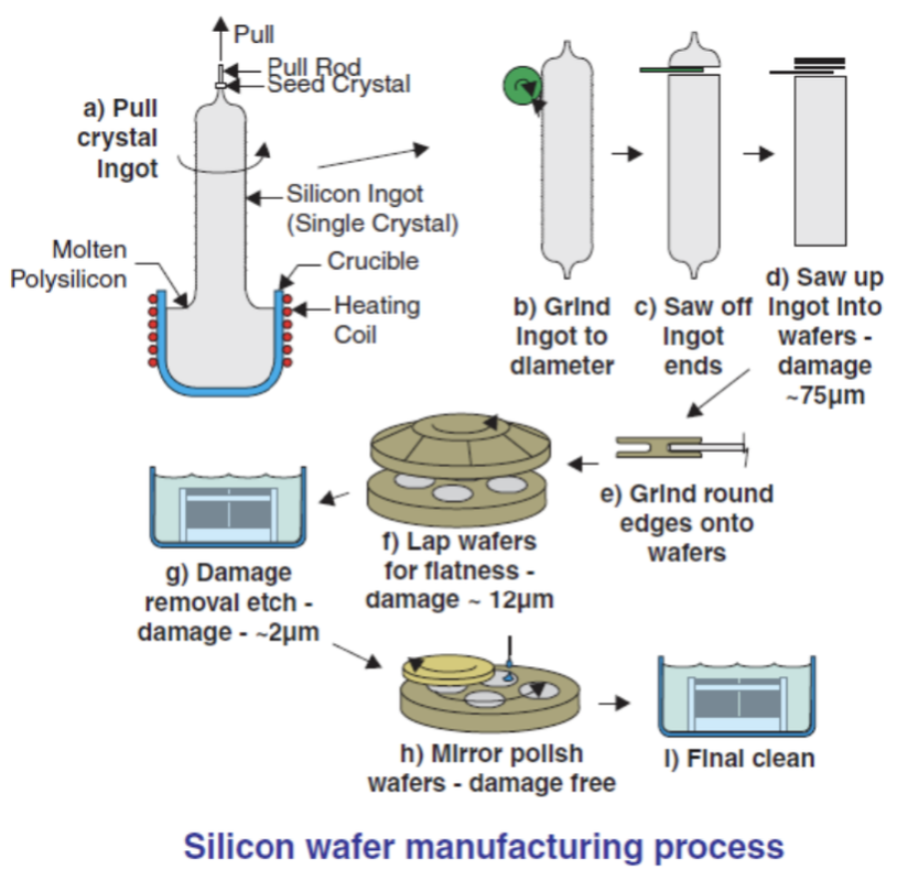
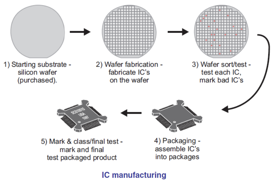
These components are so small that the entire circuit only occupies an area of less than 1 cm2. Silicon crystal wafers as the starting material, have a diameter of about 10 cm to 30 cm so that on the surface of this wafer can be made dozens to hundreds of complete circuits. For mass production even hundreds of wafers can be used at once in a fabrication process simultaneously. Of course this is very profitable in terms of cost and energy used. However, before reaching the mass production level, a series of testing processes for various production steps must be carried out carefully. In general, the process of making silicon crystal wafers can be explained by the following image:
 Initially, silicon crystal wafers were produced by IC manufacturers themselves up to the manufacture of circuits on them. But now almost all IC manufacturers buy silicon crystal wafers from third parties (suppliers).
 Currently, IC manufacturing factories or labs have developed a lot, including MOSIS in the USA, TMC in Taiwan, TIMA in France, NEC in Japan, Samsung in Korea, MIMOS in Malaysia, and many others. Generally, these companies start the process from Wafer Fabrication, which is the process of making circuits on intact silicon wafer crystals.
Wafer Fabrication
a) Cleaning
Silicon wafers must always be clean (not contaminated with organic or metal particles) in every stage of the Wafer Fabrication process. The most widely used is the RCA Clean method.
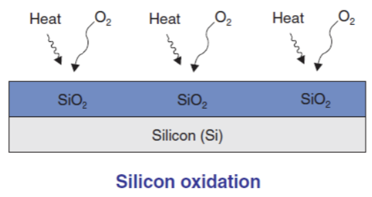
b) Oxidation
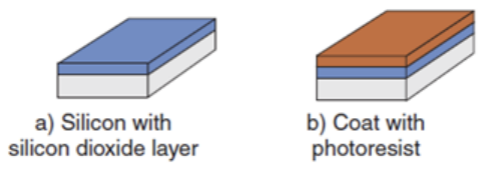
One of the main reasons why silicon is most often chosen as a semi-conductor material is because silicon offers various conveniences, including the ease of forming a high-quality insulating layer on its surface through the oxidation process. Namely, the occurrence of a chemical reaction between silicon and oxygen or water vapor at temperatures between 1000oC - 1200oC to form a Silicon Dioxide (SiO2) film layer on the wafer surface. IC Technology Journal | DENI NURMAN SiO2 is stable at high temperatures and is one of the best insulating materials.
 c) Photolithography
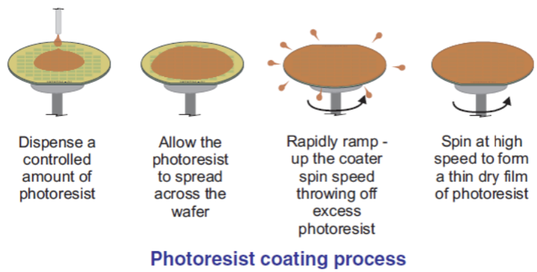
Photolithography is the main process in Wafer Fabrication, where the designed microscopic pattern is transferred from the mask to the wafer surface in the form of a real circuit. It begins by providing a layer of photoresist (a chemical liquid that is photosensitive) on the wafer surface.
 Then on the silicon wafer that has been coated with photoresist, a transparent glass plate-shaped mask/reticle is placed on top of it which has been filled with a similar circuit pattern (die) to be made, then exposed to UV light so that the photoresist layer on the wafer surface that is directly exposed to UV light will be easily peeled off with the help of a special chemical liquid. Then on the wafer surface a circuit pattern will be visible like the pattern on the mask/reticle.
 d) Ion Implantation
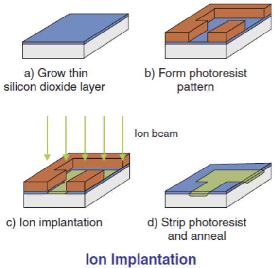
In the process of making IC, this stage is a stage that requires special control. Ion implantation is the process of implanting impurity atoms (ions) into silicon wafers that are not covered by a photoresist layer with the help of electric voltage (to regulate the depth of ion penetration) and electric current (to regulate the number of ions). The impurity atoms themselves function to change the electrical properties of the silicon wafer.
 This ion implantation technique is more widely used even though there is actually another technique to implant impurity atoms into silicon wafers called the Diffusion technique, which is a technique to implant atoms (dopants) into silicon wafers so that there is a change in their resistivity properties with the help of high temperatures between 1000oC - 1200oC. This diffusion process is similar to the process of ink spreading when dripped into a glass of clear water. When the silicon wafer is removed from high temperature to room temperature, the propagating atoms will stop propagating (in their final position).
e) Etching
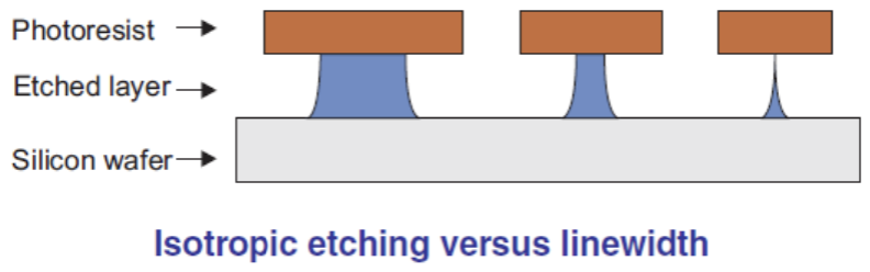
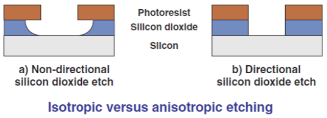
In the early years of IC technology development, the etching technique used was Wet Etching, which is by using a chemical liquid that is able to spread in all directions evenly (isotropic) to dissolve the SiO2 layer on the surface of the silicon wafer. The weakness is that the part of the SiO2 layer that is right under the photoresist layer is also partly dissolved, so it will be a problem if the pattern path is very thin.
 Along with the development of IC technology which then uses other materials such as Silicon Nitride (Si3N4) and Polysilicon where both of these materials cannot use the Wet Etching technique, at this time the Wet Etching technique has been abandoned. As a replacement, the Dry Etching technique was introduced which uses gas (fluorine, chlorine and bromine) which has an Anisotropic effect, namely the ability to decay at an uneven penetration rate.
 f) Chemical Vapor Deposition (CVD)
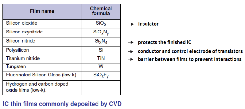
At low pressure and certain temperatures, chemical gases or vapors will react to the film layer on the surface of the silicon wafer.
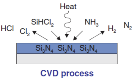 Ammonia (NH3) and Dichlorosilane (SiHCl2) gases will react to produce a solid Silicon Nitride (Si3N4) film layer with a thickness of several microns or several nanometers only. While the remaining reaction gases in the form of Hydrogen Chloride (HCl), Chlorine (CL2), Hydrogen (H2) and Nitrogen (N2) will be pumped out of the reactor.
 g) Sputter Deposition
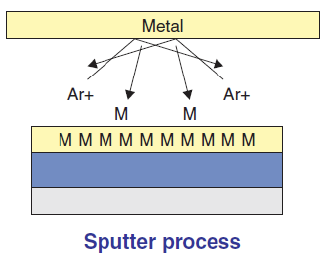
Although in general the CVD process is superior to sputtering, not all metals needed in the IC fabrication process can be formed on the surface of the silicon wafer. The sputtering process utilizes an electric field to take positive Argon ions to form a thin metal layer (film) on the target on the surface of the silicon wafer.
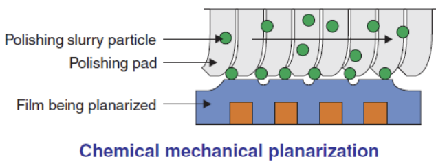
 h) Chemical Mechanical Planarization (CMP)
CMP is a combination of using chemical methods (to soften the layer of material to be removed first) and mechanical (scrubbing with polishing slurry) to remove unnecessary materials on the surface of the silicon wafer so that only the materials needed (according to the design) remain attached to the surface of the wafer.
 From all the processes that have been explained above and combined with other processes that are very numerous, one of which is Metallization (to connect all the components contained (resistors, capacitors, transistors, etc.) to form an IC circuit that is in accordance with the planned design), the final result is a number of ICs (dies) that are still united on a silicon wafer.
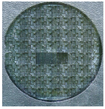
Wafer Test
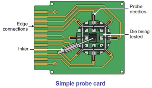
The dies produced in the Wafer Fabrication process are not 100% functional. To find out which dies are damaged, initial testing is required. Each type of die produced has its own testing tool called a probe card. This special tool is made specifically for each different type of die, but all of them are equipped with a small needle designed in such a way that it fits the position of the bond pad on the die to be tested.
 The silicon wafer to be tested is then clamped on the clamping tool on the Wafer Prober. The Wafer Prober is fully controlled by the Tester, a computerized system that can be programmed automatically to move the Probe Card to test various electrical properties on each die on the surface of the silicon wafer and then mark any die that is not functioning properly (damaged).
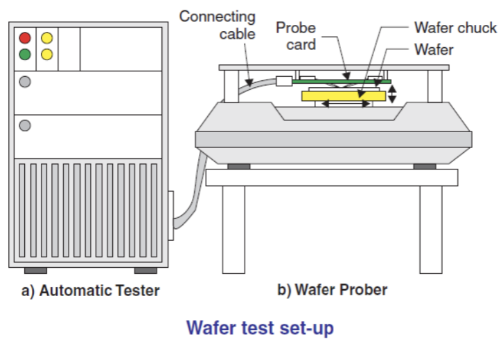
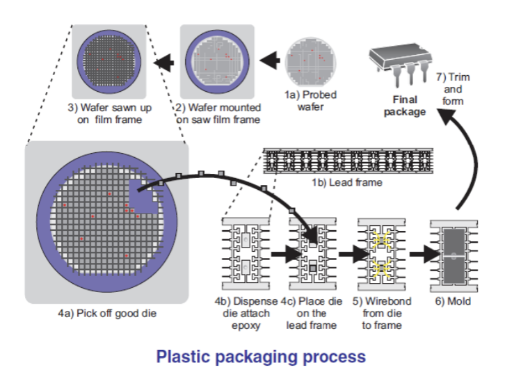
Packaging IC
Silicon that is already in die form needs careful handling because it is easily broken even though it has been given a special protective layer. In addition, the bond pad has a very small size so it is very difficult to connect with other components in an electronic application circuit. To protect the die and to facilitate handling and connection with other electronic components, packaging is needed.
a) The tested silicon wafer is placed on blue tape stretched on a flat metal surface with the back side that does not have a circuit attached to the surface of the blue tape. Then continued with cutting the silicon wafer into die pieces using a special knife (diamond-edged) at high speed. The die pieces will remain attached to the surface of the blue tape.
b) Good die pieces (that have passed the initial test) are removed from the blue tape and moved onto the leadframe (a component made of copper that functions as legs on the IC) and glued with epoxy then heated so that the epoxy hardens and the die does not come off the leadframe. The process of removing from the blue tape and moving onto the leadframe is done automatically by the machine.
c) Wirebonding, which is the process where the leadframe legs are connected to the bond pad on the die using gold wire. This work is also done automatically by the machine.
d) Molding, which is closing the lead frame using a compound that is pressed at a certain temperature and air pressure so that the die and gold thread that were originally open will be closed by the compound.
e) Solder Plating, which is the process of plating the IC legs with tin so that the legs made of copper are silver in color.
f) Marking, which is the process of labeling the IC type, part number, company name, date and so on to facilitate further identification.
 The molding technique as described above, causes the outer packaging of the IC to be larger than the size of the die inside. As a result, the high-frequency signal from the IC is slightly disturbed. To overcome this weakness, a technology has now been developed that makes it possible to produce ICs with a package size that is almost the same size as the die inside. This technique has also succeeded in improving the quality of its high-frequency signal.
The technique is called Flip Chip. In this technique, a bond pad is first made which is a pair for the connecting pad on the die to be packaged. Then, the prepared bond pad is given tin that forms small balls (bumps). After all the bond pads are filled with bumps, they are then paired with the connecting pad on the die and then heated so that both are united by the melted tin.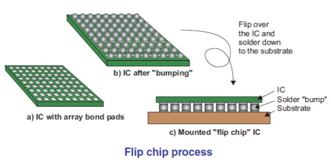
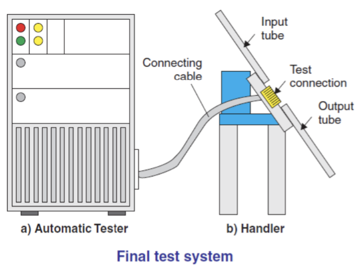
Final Test
During the packaging process, there is a possibility that the die will be damaged or the packaging process will be less than perfect. Final testing is carried out on all ICs that have been packaged so that ICs that are damaged during the packaging process are not sent together with good ICs. This final testing method is almost the same as the initial testing of silicon wafers, the difference being that finished ICs no longer require Wafer Prober but use Handlers. The Handler is also fully controlled by the Tester to test various electrical properties on each IC while simultaneously sorting the quality of each IC.
Experience as a Technician in this Industry
MT8704 Handle Technician Qualification
- The MT8704 can handle the following device types, except -> PDIP 300 mil 8 - 16 pin
- How many bin classes can be handled by MT8704iHF? -> 16 bin classes
- What is the nominal values for input power supply? -> 220 - 240 V AC
- When converting MT8704iHF from one package to another, how many parts must be replaced? -> 5 parts
- The communication tester - handler is done via ... -> the parallel tester interface, active low
- What is the maximum nominal values for temperature? -> 125 degrees Celsius
- This switch controls the minimum period of time, the Ics have to remain in the input magazine (in high temp mode) [This switch controls the minimum period of time, the Ics have to remain in the input magazine (in high temp mode)]. -> "Soaktime" switch
- Use this switch, if you want to secure the handler against misuse. -> "Key" switch
- The "Function" switch must be in this position when running production -> normal
- What control program to software reset the handler? -> Control program "000"
- What is the control program to set temperature window? -> Control program "087"
- What is the control program to program sort mode? -> Control program "088"
- What is the control program to display input (light sensor, switches) [What control program to display input (light sensor, switches)]. -> Control program "099"
- How many heaters inside the handler? -> 2 heaters
- For easy docking to the tester MT8704 have this adjustable feature, except. -> Auto positioning adjustment
- MT8704iHF can run production normally in this condition, except. -> Without SOT signal
- What is the correct position units inside the handler? -> Live bug
- Dalam model MT8704iHF, apa artinya HF (In MT8704iHF model, what does HF means)? -> HF means High Frequency
- How many contact site does MT8704iHF have? -> 1
- What is the part of the handler to shows the actual situation of the handler? -> Display
- Menampilkan pengaturan jumlah IC per tabung (Displays the amount setting of ICs per tube)? -> "Tube capacity" switch
- In the case the "sortmode" switch is in position, the handler chooses automatically free sorting channels. The handler chooses a certain bin category, as long as no more than 14 different bin categories are used at the same time. -> position 1
- When running production "fast run" control program must be ... -> off
- Apa fungsi dari program kontrol "090" (What are the function of control program "090"). -> Test input magazine setup and position
- Saat sakelar "soaktime" disetel ke "010", artinya ... (When "soaktime" switch set to "010", it is means ...). -> soak time 1 minutes.
MULTITEST Handler Technician Qualification
- How many test sites are present in MT9308 handler? -> 2
- Apa artinya LFS (What does LFS stands for)? -> Loader Feed Shuttle
- What is the part that distributes the devices to contact site one and two and also able to move in horizontal and turn positions? -> Feed shuttle
- What is the part that connects the device under test and test head equipment and also covers the temperature chamber for hot and cold control? -> Standard KE
- What part of the equipment is responsible for the following operations? Receiving the singulated device, positioning with contact/edges and transport the device forward to the contact springs of the KE. After bin result releasing device to output segment. -> Standard KC
- Empty containers used for chemicals and other hazardous materials shall be considered as (Empty containers used for chemicals and other hazardous materials shall be considered as). -> hazardous
- What tool must be connected to interface port labeled tester for binning integrity check procedure? -> Bin Simulator
- What switch must be pressed to power off the multitest handler? -> Main Power Switch labelled "O"
- What message is shown to screen after handler has initialized? -> Start Up Done
- How many test sites are present in MT9320 handler? -> 4
- What switch must be pressed on keyboard to show menu 'set up'? -> F3
- Kapan kami memeriksa PM / CAL Sticker di handler (When do we check PM/CAL Sticker at handler)? -> Every nite shift
- What tubes orientation must be placed to handler when we load? -> Side Ways
- What is SOT (What is SOT stands for)? -> Start Of Test
- Responsible for automatic replacement of filled output tubes with empty ones at output tracks 5, 6 7 and 8 are... -> Auto tube
- Reflective photosensor mounted under the tube loading surface which detects the presence of a tube of device in the loader gripper. -> Tube sensor.
A5xx Handler Technician Qualifications
- How to print a datalog file stored in User Computer of Teradyne A585?-> Type "lpr" space, followed by the file name and then press return.
- What's the sequence to power up tester Teradyne A550/A585?-> AC Main Power, Mainframe Main Power and then Test System Power.
- After the production lot completed, how's to get the production summary?-> Click "endlot" button
- Which one is the valid lot naming to indicate setup verification run of sublot "W-1234.2/9"?-> W_1234_2_9V
- If Correlation Units fail during setup, what's action we should take?-> Perform OCAP for correlation test problem.
- As per OCAP of Teradyne A550/A585 Diagnostic and Calibration, what should you do if the calibration fail?-> Perform validation until 3 times.
- In A500, mixed signal cabinet comprised of formatter card cage, conversion card cage and?-> Vector bus card cage
- During MI continuity checker, a special board is required to plug to the test head and called?-> AD989 (DIB board)
- Allows the passage of a right or left driving boards signal through it self to a terminator?-> Pass through board
- It decodes digital pattern data received through vector bus II, defines wave shape, and assigns timing information for the programmable edges?-> Digital formatters
- It provides the A550 with the ability to source and capture waveforms in both the analog and digital domains?-> Wave form subsystem.
- Formatter card cage is using majority of this power supplies?-> Switching
- What operating system does the A500 use?-> Unix
- Digital vector pattern rate and analog waveform sample rate are controlled by different clock defined form?-> Time master high frequency clock
- A part of the tester that monitors the electrical and temperature condition within the system and shutdown it down once abnormal condition is detected?-> Environmental monitor board
- To achieve a fast program development A500 uses?-> Dual computer architecture
- Without the environmental monitor board, A500 can still run?-> TRUE
- There are two types of DC sources available in A500 system?-> Matrixed and non -matrixed
- Electronic cards and formatter board pins are working in pair?-> TRUE
- SMEM adalah singkatan (SMEM stands for)?-> Source memory
- CMEM stands for (CMEM stands for)?-> Capture Memory.
DAYMARC Handler Technician Qualification
- Board mana yang salah pada pesan "BOARD 1 ERROR" (Which board is faulty on a "BOARD 1 ERROR" message)? -> Shuttle Board
- Board that controls the vertical and horizontal movement of the distributor. -> Bin control board
- Part on the handler that holds tubes of parts and waiting to be tested. -> Infeed stacker
- Takes tubes from gripper and cycles parts to the infeed singulator track. -> Robot arm
- Board used to control the movement of robot, stripper & gripper stepper motor. -> Feeder board
- Board that gives handshaking signal to the tester. -> Interface board
- Unloads the tested parts from the test track and sort them to the proper unload bed track. -> Distributor
- Part of the main control panel that sets the desired test temperature in the positive or negative degrees centigrade. -> Set point thumbwheel
- When pressed, this switch disengages power to the Robot, Gripper, and Stripper motors. -> Loader access
- A twenty character vacuum fluorescent display that indicates system status and maintenance information. -> Alphanumeric display
- Responsible for automatic replacement of filled output tubes with empty ones at output tracks 7 and 8. -> Auto tube
- In Daymarc tri-temp handler, during operation the handler performs the following except for. -> Device are tested after soaking on the unload bed.
- Part of the infeed stack that releases the device one at a time to chamber. -> Infeed singulator
- Board error # 4 corresponds to. -> Error on Temp. control board
- What self test number is used to activate test site solenoids and bellows either ON or OFF state? -> Self test # 2, test site valves
- CDA requirement of Daymarc handler during low temp. operation. -> 55 - 60 psi
- TRACK ENTRY BLOCKAGE indicates that a device is (TRACK ENTRY BLOCKAGE indicates that a device is). -> Blocking the track entrance sensor of the unload bed
- Reflective photosensor mounted under the tube loading surface which detects the presence of a tube of device in the stripper arm. -> Tube sensor
- On Self Test 6 menu, what does XX0XXXXX mean? -> Distributor exit sensor 3 is unblocked.
- Temperature sensor TS1 can be found on (Temperature sensor TS1 can be found on) -> Test site near actuator (Test site near actuator).
- When a jam occurs in the handler, we can see the locate of jam at... -> Sequence Indicator Display.
SYMTEK Handler Technician Qualifications
- Apa bagian utama dari handler SYMTEK 300 (What are the main parts of a SYMTEK 300 handler)? -> Input Chain, Storage, Test Site and Sort
- What is the communication link between the master CPU and the 3 slaves? -> RS422
- Nama 3 budak dari 300 SYMTEK (Name the 3 slaves of a SYMTEK 300). -> Handler Slave 6803 Processor, Sorter Slave 6803 Processor, Temp. Control 68701 Processor
- How many low power motors can a single MPU board control and drive? -> 1 Motor
- How many high power motor driver boards does SYMTEK 300 have and the corresponding motors that used it? -> 3 Motor, Turn Table Motor, Test Site Singulator, Sort Chain Motor
- What is the lead straightener Assembly used for? -> For rework any little bent lead
- Di mana letak 2 fail aman dari SYMTEK 300 (Where are the 2 fail safe of the SYMTEK 300 located)? -> Storage & Test Site Chamber
- Slave processor controls tester communication while human interface and statistics is being controlled by what board? -> Master CPU
- In the case of the handler slave which can control and drive one motor, what board controls the rest of the high power motor under the handler slave responsibility? -> Small stepper motor driver board
- Nama MPU budak yang terhubung langsung (RS422) ke CPU master (Name the slave MPU which is directly linked (RS422) to the master CPU). -> Handler Slave, Sorter Slave and Temperature Controller
- It refers to the fiber optic light conductors used for remote optical sensing. -> Lite Pipes
- It is a metallic or non-metallic sub-assembly which carry devices from test output track to the sort bins. -> Sort Bucket
- It is known as the complete assembly of sort buckets. -> Sort Chain
- It is the time that the system will delay by before automatically sorting all parts in the chain to their assigned bins. This time starts whenever a part is dropped into the chain from the contactor. -> Chain Wait Time
- It is the minimum time (in seconds) that is required for the parts to remain in the storage. -> Soak Time
- A command to examine every bucket in the chain to insure that it is empty. This command can be given at any time. -> Purge Chain
- A command to open and then reclose the contactor. -> Reprobe
- It is the time constant for the simulated mass probe for the chamber last selected by the chamber parameter. It ranges from 0.0001 to 0.9999. -> Mass Factor
- The LN2 pressure for Symtek 300 Handler should not exceed (The LN2 pressure for Symtek 300 Handler should not exceed). -> 50 psi
- It is the time delay between when a part is dropped into the contactor and when the contactor is allowed to close on the part. -> Contactor Settling Time.
SYNAX Handler Technician Qualifications
- If you find a unit on the floor near a handler which being used by production operator, you should treat the units as ... -> A Stray Unit.
- What things should be done if you find a stray unit? -> Give the unit to operator and tell her to put it in a reject tube/tray and put label on the tube/tray "Stray" (Give the unit to operator and tell her to put it in a reject tube/tray and put label on the tube/tray "Stray").
- Is it allowed to do manual transfer from tube to tube on final test production line? -> No. It is not allowed for both good and reject units.
- If there is an over rejection during production testing, what is the first thing to check before using the handler? -> Make sure that there is no unit left in the handler.
- What are the types of package that Synax 121/1201 can handle? -> QFP, TSOP, TQFP and BGA.
- What are 3 optional mechanical parts of Synax 1201? -> Input 90° rotator, Cooling Station and Output 90° rotator.
- What does the 'Pitch' on the tray parameter mean? -> The distance from the center of the package to the center of adjacent package.
- What menu can be used to check the functionality of the sensors on Synax 1201? -> I/O monitor
- The part that is not replaced during conversion is? -> input transfer
- These parts are driven by motor except for (These parts are driven by motor except for). -> input shuttle
- What is the function of the contact supply? -> transfer the unit to the contactor.
- What part of Synax 121 can be bypass during production run? -> preheat assembly
- How to set tray parameters for input and output trays 1, 2, and 3? -> Access the MENU 2 & choose tray parameter . Press any of the desired tray (input tray 1, 2, & 3) [Access the MENU 2 & choose tray parameter . Press any of the desired tray (input tray 1, 2, & 3)].
- What is the minimum pressure of compressed dry air (CDA) for Synax 121/1201-H? -> 4 KgF/cm2
- How to set the handler at exercise mode? -> Access the MENU 2 & choose "Mode Change", select offline option in the Sub-MENU.
- What does the 'test time out error' on the test parameters menu mean? -> The maximum time period between SOT from handler and EOT from tester.
- What is the correct sequence to download a data from IC Card to handler? -> Insert an IC card to the handler. Access MENU 2 & choose 'IC card Operation'. Choose the desired file then press LOAD. Press ENTER.
- What is the correct sequence to save data on IC Card? -> Insert an IC card to the handler. Access MENU 2 & choose 'IC card Operation'. then press READ. Specify desired file name. Press ENTER.
- How many sites does a Synax 121/1201 have? -> 2
- How many binning categories can Synax 121/1201 receive? -> 8
- For Synax 121/1201, what contact mode must be use to test 2 units at the same time? -> CD mode
- Does PS supply all sensors and solenoids for both Synax 121/1201? -> 24VDC
- What is the maximum no. of insertion allowed which is being monitored by ASUC (auto stop unit) counter? -> 25K.
AETRIUM Handler Technician Qualifications
- If you find a unit on the floor near a handler which being used by production operator, you should treat the units as ... -> A Stray Unit.
- What things should be done if you find a stray unit? -> Give the unit to operator and tell her to put it in a reject tube/tray and put label on the tube/tray "Stray" (Give the unit to operator and tell her to put it in a reject tube/tray and put label on the tube/tray "Stray").
- Is it allowed to do manual transfer from tube to tube on final test production line? -> No. It is not allowed for both good and reject units.
- If there is an over rejection during production testing, what is the first thing to check before using the handler? -> Make sure that there is no unit left in the handler.
- This specifies the minimum amount of time, in seconds, that device must remain in input track to "soak up" enough heat for admission to the test site. -> Soak Time Set
- HTR means that temperature continue to rise even though CPU is commanding it to be off while "htr" means _ -> Heater is open or disconnected.
- This mode provides for activating and testing the test ledge, the Customer interface board, the singulator and the input Gate? -> Calibrate / Actuate Mode
- This is the part of the AETRIUM handler, where the actual testing of device takes place. -> Contactor Device Assembly
- It is composed of stepper motor and a pulley and corded belt driven shuttle. -> Sort Assembly
- Ten LED's on the Input tube adapter indicate the status of each track ____ means the device in the track are feeding through the input Gate. -> Blinking rapidly
- The part of the handler which directs the operator to the location of the problem. -> Control Panel
- This handler board contains the "main" Z80 CPU, its memory, clock and reset; plus the chip selects, address buffers and data transceivers for communicating on the I/O data bus. -> CPU board
- The CPU uses this board to control the input and shuttle stepping motors. It is also the source of the 4ms interrupt. -> Timing board
- This mode is used to select an alternate message language, to test and adjust the input and shuttle assemblies and to access the I/O areas or memory of the CPU or micro-processors. -> Diagnostics Mode
- It is a delay, up to 99 seconds in 4 millisecond increments, which can be inserted between singulating and contact closure. -> Extra Settle Time
- This message means that all bins assigned to the current sort are filled and bin full lights are blinking. -> Empty indicated bins
- The AETRIUM 5050S handler is designed for medium to high volume testing of Small Outline Integrated Circuits (SOIC) and can sort package from. -> 8 to 30 leads
- Each of the seven heater zones in the 5050S incorporates a heater and a 100 ohms platinum RTD sensor. RTDs will read approximately ______ ohms at room temperature. -> 109 Ohms
- This provides the control interface between the handler and the tester. -> Customer interface board
- AETRIUM 5050S is capable of handling this temperature range. -> 40°C to 155°C
- This means to start handler operation? -> Run
- This key causes the set-up information to be stored or to change on-off status? -> Enter
- Up to how many times the Operator can perform Handler Validation (after repair) before the machine is shutdown? -> 3 times
- What type of units must be used during Handler Validation after handler is repaired due to bent lead? -> Dummy Units.
Teradyne Catalyst Technician Qualifications
- What does V/I source mean (Apa artinya V / I)? -> Voltage Current source
- What does TIP mean (Apa artinya TIP)? -> Test In Process
- What is the Operating Temperature for Catalyst to function properly? -> 20 - 30 degress C
- What is the RH requirement for Catalyst to function properly? -> 40 - 60%
- What is the maximum number of V/I Matrix source of Catalyst (Berapa jumlah maksimum V / I Matrix sumber Catalyst)? -> 5
- CDM stands for (CDM singkatan)? -> Catalyst Digital Mainframe
- What is SPARCAL (Apa itu SPARCAL)? -> S-Parameter Calibration
- What is TSY (Apa itu TSY)? -> Trigger Switch Yard
- What is DMM (Apa itu DMM)? -> Digital Multitmeter
- What is DIB (Apa itu DIB)? -> Device Interface Board
- What is the meaning of PACS (Apa arti PACS)? -> Precision AC Subsystem
- What is the meaning of DOA (Apa arti DOA)? -> Defective On Arrival
- What is the meaning of SWPS (Apa arti dari SWPS)? -> Switching Power Supply
- What is the meaning of APU (Apa arti APU)? -> Analog Pin Unit
- What is the freq. Of the master clock (Apa itu freq. Jam master)? -> 10 Mhz
- What is the meaning of TMS (Apa arti dari TMS)? -> Time Measurement Subsystem
- How many channels does the CDTH card (How many channels does the CDTH card have)? -> 8
- What station should be used when running production (What station should be used when running production)? -> Station 1
- Where is the location of Test System Power Switches (Di mana lokasi Test System Power Switches)? -> Power Control Panel
- Command used when halting all computer processes (Command used when stopping all computer processes)? -> halt_sys
- It is the location of all tester channel cards (Ini adalah lokasi semua kartu channel tester)? -> Test Head
- Connector to place the multimeter test probe when measuring power supplies (Connector to place the multimeter test probe when measuring power supplies)? -> Molex Connector
- Checker to run to check micro wave option (Checker to run to check micro wave option)? -> uw_st
- Instrument to be used when performing DCREFCAL (Instrument to be used when performing DCREFCAL)? -> DMM
- DUT means (maksud DUT)? -> Device Under Test
- Test Head Digital Power Supply is located (Uji Kepala Power Supply Digital berada)? -> Below Test Head cable Trunk (Dibawah Uji Kepala kabel Trunk).
Electrostatic Discharge (ESD) Technician Qualifications
- Through what means can electrostatic / static electricity occur? -> polarization and friction of electrically charged objects.
- How often is the wrist strap inspection performed? -> once per shift.
- What is the name of the tool used to neutralize static charges around machines related to ESD? -> ionizer.
- What are the expected work area conditions related to ESD? -> Controlled ESD.
- What is the effect of ESD on devices? -> can damage the function of the device.
- Which statement about ESD is most correct? -> electrostatic charge transfer event.
- Is the function of the wrist strap related to ESD? -> discharge the charge from the human body to the earth.
- What is the closest distance allowed between the IC and another non-antistatic object? -> 6 inches.
- What should be done / controlled to ensure that the workbench is ESD free? -> check the grounding cable.
- What is the name of the tool used to check the wrist strap? -> wrist strap tester.
- How can electrostatic charges occur? -> 2 objects rub against each other / are close together and then suddenly separated.
- Which of the following statements could possibly cause damage to the unit due to ESD? -> handling the device without using ESD equipment.
- What to do after checking the wrist strap? -> charge the wrist strap daily monitor.
- What is the function of grounding on a production table/machine if it is connected to an ESD event? -> discharge electrostatic charges to the earth.
- Which of the following causes ESD in the work area? -> rubbing the unit.
- If a human hand without a ground strap holds the device, it will cause damage to the device, for the explanation! -> because the electrostatic charge on the human is transferred to the device.
- Which of the following is one of the models that can cause ESD? -> human body, machine model, device charge.
- Which of the following items should not be in an ESD-free work area? -> paper, tissue.
- What equipment should be worn when touching the IC? -> heel strap, wrist strap.
- What equipment is needed in the work area to protect devices from ESD? -> air ionizer.
- Why do we need to check the wrist strap / heelstrap when entering the work area? -> to ensure it works or not.
- If your wrist strap is damaged / your grounding machine is found to be loose, what should you do? -> replace or repair
- Why is ESD control so important in the semiconductor industry? -> because the material is sensitive to electrostatic charge transfer.
- All employees must use this... -> StaticSorb® Electrostatic Protective Clothing.
- What is the spec number about ESD ? -> 3017.
- What tool is used to check the grounding cable? -> multimeter.
Statistical Process Control (SPC) Technician Qualifications
- What type of problems should be analyzed? -> those related to control machines that often occur on the line
- The level of seriousness of the effects caused by a problem/failure on customers is something that needs to be considered in ? -> FMEA
- Which of the following is included in the TCM category? -> On line control tool off line of PM improvement tool.
- What is meant by LCL? -> The lowest value that is still allowed to be processed.
- Which of the following is included in PM? -> PM schedule, PM checklist, PM procedure.
- What is the function of the severity table? -> To find out how serious the problem is.
- FMEA is grouped into what category in TCM? -> off line improvement tool
- Which of the following is included in the attribute control chart? -> p chart, np chart, c chart, u chart.
- Which of the following is included in the variable control chart? -> xbar r chart, xbar s chart, x-mr chart.
- What type of problem should be analyzed? -> how serious is the problem found by the customer.
- What is meant by customer? -> every user, recipient, forwarder, processor, work forwarder.
- What is meant by UCL? -> the highest value that is still allowed to be processed.
- What is the purpose of TCM? -> motivate employees, production monitor, control the process systematically.
- What is the function of the occurrence table? -> to find out how often a problem occurs.
- What is meant by OCAP? -> systematic flow that shows priority actions to be taken.
- What is the purpose of using FMEA? -> solve problems and find their causes.
- What are the 2 quality strategies used in production? -> detection and prevention.
- What is meant by OCAP? -> systematic flow that shows priority actions to be taken.
- Which of the following is the formula used to determine how serious the problem is? -> RPN =SOD ( 1- 1000).
- Which of the following is included in ONLINE CONTROL TOOLS? -> control chart, ocap positrol, plan checklist, check sheet.
- What does FMEA stand for? -> failure modes and effects analysis.
- What are the 2 types of control charts used in production lines? -> attribute and variable.
- What kind of problems does PT AIT analyze using FMEA? -> process FMEA.
- What is our company's quality policy? -> provide the best service to meet and exceed customer expectations.
- What type of FMEA is used in PT AIT? -> process.
- Which of the following is included in OFF LINE IMOROVMENT TOOLS? -> FMEA GRR study MPC ps.
- Why do we need SPC? -> customers want products with zero defects.
- What is the use of CAL? -> to record corrective actions taken.
- What is one of the advantages of using SPC? -> increase productivity.
- What is the use of patterns on a control chart? -> to determine whether the control machine is in a stable state or not.
- What are the 2 types of control charts used to control processes? -> variable and attribute.
- Which of the following is a factor of variation causes? -> man, method, material, machine, environment.
- which of the following is the standard normal distribution N=0 SD=1 (SMALLEST SD) ? -> mean 0 std deviation 1.
- Which of the following is the best condition for PMC spec with oven temperature 175 +/- 5 der C? -> 175 standard deviation 0.
- What is the full form of PADACA? -> plan do check action.
- What is the best step in PADACA after corrective action is done? -> analyze the results, do documentation.
- What does GRR stand for? -> gauge repeatability reproducibility.
- When should the measurement system be revised in relation to the GRR study? -> %R&R>10
- Which are the correct & orderly steps to handle variations caused by ASSIGNABLE CAUSE ? -> turn off the machine, conduct investigation, take corrective action, find the cause of the AC.
- Which of the following are three types of variation based on events? -> piece to piece, time to time within piece.
- Which is an example of UNNATURAL PATTERN? -> 8 consecutive dots on 1 side of the center line.
- A diagram that shows the systematic relationship between an effect & all possible causes that influence it is called ? -> cause and effect diagram.
- In SPC, we know the term "MEAN", what is "MEAN"? -> the average value of a process data.
- In SPC, we know the term "standard deviation", what is "standard deviation"? -> deviation of a process.
- What is meant by repeatability in GRR study? -> variation after repeated measurements.
- What is meant by reproducibility in GRR study? -> variation after measurement achieved by different operators.
- Why should we conduct MSA (Measurement System Analysis) study? -> ensure the tools used provide accurate and stable values.
- Which is the definition of variation? -> diversity of quality of a product.
- What is meant by "SPEC LIMIT" is ? -> the limit determined by the customer / engineer based on the spec.
- What is meant by "TARGET VALUE" is ? -> value in the middle of the spec limit.
- Why do the points fluctuate randomly on the control chart during stable conditions? -> because of a change cause that is difficult to determine.
- In the control circle, we are familiar with the "PLAN" steps, which steps are included? -> goal / target problem.
- Which one is included in the 7 statistical tools (SEVEN TOOL)? -> Pareto diagram.
- What is the acceptance criteria if the % R&R obtained is greater than 30%? -> not accepted unless approved by top manager.
- Among the 7 statistical tools, we know one of them is "CHECKSHEET", which in its application is used for ? -> to identify problems.
MCT Handler Technician Qualifications
- How many motors are present on this type of handler? -> 3.
- How many displays are present on MCT handler for the models 3608 and 3616 ? -> 37 for 3608 and 56 for 3616.
- How many detectors are there on MCT handler models 3608 and 3616 ? -> 37 for 3608 and 53 for 3616.
- In the card cage of the handler for the 3616 model, what board is present on slot #5 ? -> Analog I/0 BD.
- Which CPU of these handler continues the priorities input by FIFO and soak times? -> CPU 1.
- On the Rocker DIP switch that use to run diagnostics on the handler, what is the function of switch #2? -> Out of temperature disable.
- What kind of interfacing if the connection of handler and tester is to send the test ready signal or to receive bin category signal? -> Digital Interface.
- Which CPU of the handler controls three major machine function switches such as input (input solenoid activation and conveyor motor) sorter control and output reservoir? -> CPU 3.
- What setting of diagnostic switches can be used to check all detectors of the handler? -> 1 and 8.
- MCT 3608/3616 Model has the capability to handle IC PDIP packages, of what body width size? -> All of the answer are correct.
- In the operating mode switch, what is the setting if the handler operator is in conjunction with tester? -> Normal
- What power supply is present on 3616 model but not on a 3608 model? -> 2 Amp constant PS.
- Which power supply is a 6 amp. regulated source that provides power to the logic and optic circuits? -> 5V PS.
- On the operating switch, what is the setting if the handler contacts remain closed on device under test? -> Calibrate.
- On the temperature display, what is the corresponding trouble if it is shows --99.9 reading ? -> RTD shorted to ground.
- What setting of diagnostic switch that can be used to check motors and its alignment? -> 1, 3 and 8.
- Apa tujuan dari Diag. Uji "0" (What is the purpose of Diag. Test "0") ? -> To check the function of each CPU (Untuk memeriksa fungsi masing-masing CPU).
- At 0°C, what is the normal resistance reading of the sensor RTD? -> 100 ohms.
- During diagnostic checking of detectors, which display showing the test site stage detector problem ? -> Stop display.
Aseco ASC130 Technician Qualification
- Apa enam bagian utama dari Aseco S-130 handler (What are six major parts of the Aseco S-130 handler) ? -> Autoloader, Storage Chamber, Prober, Binner, Vacuum System and Operator Console.
- Apa tiga pompa Vakum dari Aseco S-130 handler (What are three Vacuum pump of Aseco S-130 handler) ? -> Vacuum Chuck for prober, Hold Position for output track, Binning Shuttle.
- What is the function of Optional I/F Bus CPU board? -> To extract various information.
- What is the function of the Interface board? -> Control the link or a digital communication between tester and handler.
- What is the function of CRT Control board? -> Control the video signal for CRT monitor.
- Which board has function to Handles the temperature information as sensed by the RTD sensor? -> Temperature Control Board.
- Which board has the function to control the overall system functions, because all the incoming signals from each board in the cage will be analyzed and processed through this board? -> Master CPU.
- What is the correct value for encoder position Reading for "LOAD" of prober ? -> 768 ± 1.
- What is the correct value for encoder position Reading for "TEST" of prober ? -> 1312 ± 1.
- What is the correct value for encoder position Reading for "UNLOAD" of prober ? -> 0 ± 1.
- During "ON" state, the Bin Shuttle Vacuum Detector voltage level should read how much ? -> 3.80 +/-0.2V.
- Selama status "OFF", level tegangan Prober Vacuum Detector harus membaca berapa banyak (During "OFF" state, the Prober Vacuum Detector voltage level should read how many) ? -> 2.00 +/-0.2V.
- How many units must be run during the binning integrity check? -> 200 units.
- The Temperature Zero Adjust on Temp. Control Board adjustment must be set to how many volts ? -> 200mV +/- 1mVdc.
- How many jam rate requirement to ensure that the handler runs smoothly and pass? -> 1/2000 jam rate.
- What if we want to check the grounding strap we use... -> Using a Digital Multimeter.
- What is SOT (What is SOT stands for) ? -> Start Of Test.
Electroglas System EG2000 Technician Qualification
- What is Camera Control Unit ? -> It provides control and power signals to the auto align camera to the OCR and PMI cameras.
- What is Cassette/Carriers ? -> It is a container holding up to 25 wafers each which fit the indexer and the wafer platforms.
- What is Chucktop ? -> It is the surface of the chuck where the wafer sits on during probe.
- What is Clear zone ? -> It is the recommended area around the wafer ID characters.
- What is Forcer ? -> It is known as the movable half of the linear motor which carries the Z stage and chucktop on an air bearing over the platen.
- What is a Joystick? -> A control lever which manually controls the positioning of the forcer.
- What is Material Handling Option ? -> It is an optional module which automatically transports, pre-aligns, transfers and unloads the wafer.
- What is Pre-Align ? -> It is a process of positioning the wafer so that all flats will be in the same position.
- Apa persyaratan pneumatik dari EG Prober (What is the pneumatic requirements of EG Prober) ? -> 18 to 25 in Hg.
- Where is the flat wafer located if the flat position is set at 0°? -> Down.
- If one of the requirement of EG Prober is removed, and you can't use the EG what will you do ? -> Check all the required power/air/vac & set-up prober.
- What is the power supply needed on EG Prober 2001X? -> 110/220 Vac 50/60 Hz.
- What is the air pressure requirement of the EG Prober 2001X? -> 75 Psi.
- EG Prober 2001X is used for (EG Prober 2001X is used for) ? -> Wafer Sorting.
- What is the allowable area of the broken wafer the EG Prober 2001X can still handle and probe? -> 50% or more.
- On the EG Prober 2001X power control module, which board is responsible for the movements of the forcer to what speed, direction and location? -> XY motion control board.
- What is Automatic Align Option ? -> This is an optional module which performs automatic wafer alignment prior to probing operation by means of pattern recognition.
- What causes Blank The Motor ? -> A process that causes all electronics driven motors to go to zero volts, thereby allowing the forcer (XY motor) to float (non-registered) [A process that causes all electronics driven motors to go to zero volts, thereby allowing the forcer (XY motor) to float (non-registered)].
- What is our company's commitment as mentioned in the Environmental Policy? -> To protect its employees and the surrounding communities from hazards related to our activities and products.
- What is the function of grounding on a production table or rack? -> To transfer electrostatic charge to the ground.