 NFT Collections")

Database system modeling can be done through a conceptual design approach, namely the Entity Relationship Diagram (ERD or Er Diagram).
Entity Relationship Diagram (ERD) is a diagram that describes the relationships between entities.
An entity is an object that exists and can be distinguished from other objects that can be identified in the user environment.
Each entity has attributes as a description of the entity, for example the student entity, which has the attributes: student ID number, name and address.

ERD notation example
Cardinality Relations & Ratios
Describes the limits of the number of connections between one entity and another entity. Cardinality Ratio Types.
1 : 1 (One-To-One)
An entity A is associated with an entity B, and an entity B is associated with at most one entity A.
1 : M (One-To-Many)
An entity A is associated with a number of entities B, but entity B can be associated with at most one entity A.
M : 1 (Many-To-One)
An entity A can be associated with at most one entity B, but an entity B can be associated with any number of entities in A.
M : M (Many – To – Many)
This relationship shows that each entity in entity set A is related to many entities in entity set B. And each entity in entity set B is related to many entities in entity set A. This relationship is a combination of One-to-Many and Many-to-One relationships.
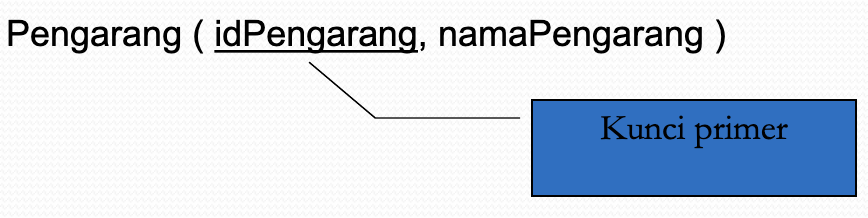
Key
Each entity has a primary key. A primary key is an attribute or set of attributes that distinguishes each row in a relation. Primary keys are usually indicated by an underscore.
Mapping ERD to Table
ER Diagram Transformation to Relationship
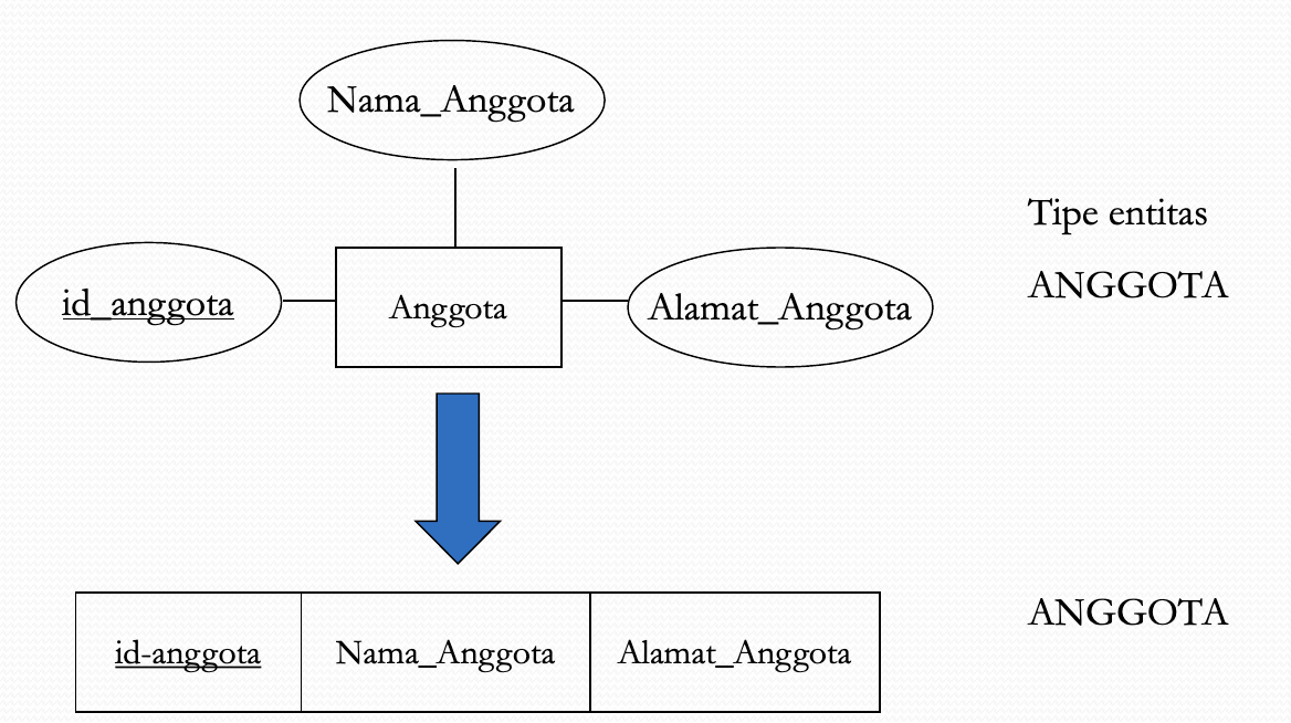
Mapping Entities
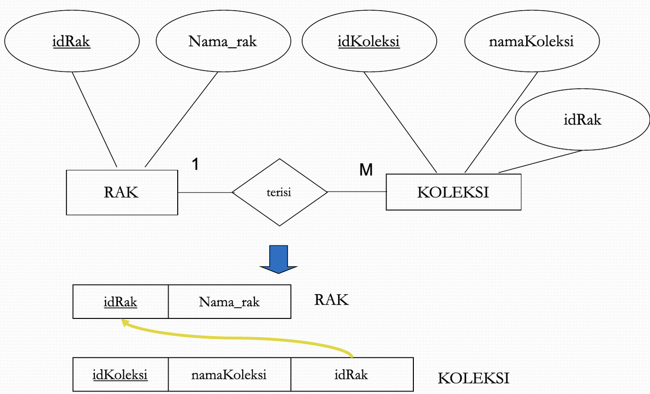
1 to M Relationship Mapping
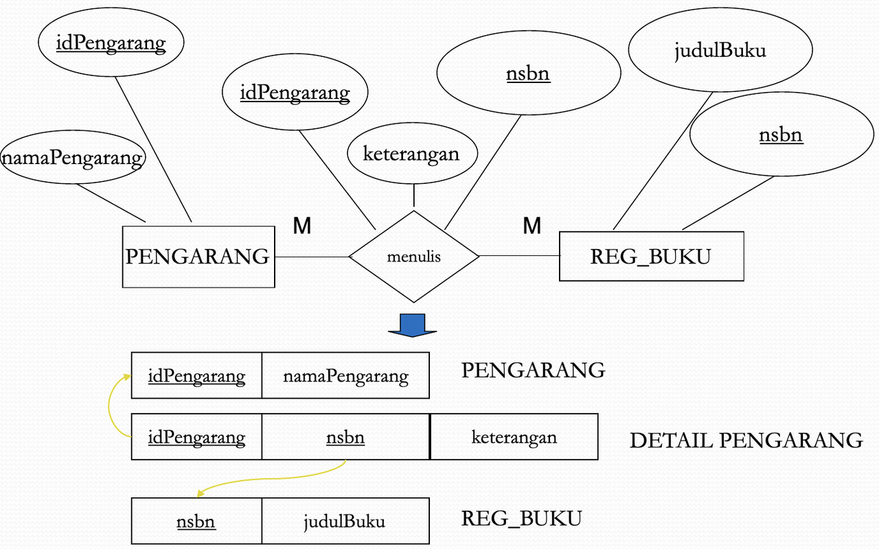
Mapping M to M Relationships
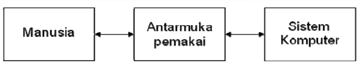
User Interface Design
It is a part of the system that is controlled by the user to achieve and implement the functions of a system. The user interface combines elements of the system, the user and the interaction between the two.
Approach Method
Types of application programs:
- Special purpose software
- General purpose software.
User-centered design approach: designers and users together create the interface. User design approach: only users create the interface. centered design approach: only designers create the interface.
Special Purpose Software
Namely, application programs for special purposes with special users (special purpose software). User groups can be easily estimated, both in terms of expertise and the variety of interfaces to be used. For example: warehouse inventory programs, student academic data management, hotel reservation services.
Approaches used:
- User-centered design approach
- User design approach.
General Purpose Software
It is an application program that will be used by various user groups. The designer can 'force' the user to accept the interface, although it can have an impact on the program not selling. One way that can be done is that the user can change the appearance according to their own wishes (customization), for example: changing the basic color, desktop settings, wallpaper, screensaver, etc.
The approach used is a centered design approach.
Things to consider when creating a user interface:
User friendly
good interface, easy to operate, easy to learn and users feel comfortable using the interface.
High quality
so that it can circulate widely, be admired by many people and often imitated.
User interface properties
Flexibility
- The system must be able to adapt to user desires
- by providing opportunities to fulfill personal needs
- customizing system
- The flexibility factor will pamper users so that they can get what they want.
Consistency
- Consistency should be applied to all aspects of user interface design.
- Layout: consistent use of displays so that users know where to look for instructions, error messages and status information.
- Commands: related to the use of command/instruction names, standard keys and syntax. For example: ESC is always used to cancel and F1 is always used to display help.
- Data entry format: use a standard format that is easy for users to understand.
Feedback
A good program is a program that can provide feedback to the user about what will be done, what is being done, what has been done. Example:
- If the program requires input, what input does the program want at that time?
- Produces a visible change in the interface, e.g.: “MAIL HAS BEEN SENT” when responding to “SEND”.
Efficiency
Efficiency in computer systems involving human-computer performance together, throughput (average speed).
Impact of good interface design:
- Increased productivity
- Reduce employee training costs
- User satisfaction.
Getting to Know Entity Relationship Diagrams
Clues:
- ER (Entity-Relationship) diagrams are commonly used in the analysis stage of database design.
- Used as a tool to communicate between database developers and users.
- An ER diagram is a conceptual data model, which represents data in an organization in the form of objects and their relationships.
- It does not depend on the software that will be used to implement the database.
- So far, there are many notation models used to create ER diagrams.
1. ERD and Database Design Process
Three database design processes related to ERD:
- Needs analysis. Digging up data needs for information presentation.
- Conceptual database design. Presents the data requirements to be stored in a high-level form (e.g. ERD)
- Logical database design. Selecting a DBMS and converting to a database schema.
Three Other Stages of Database Design
- Schema Repair. Identify potential problems and make corrections.
- Physical database design. Aligning the database design with the features in the DBMS.
- Security design. Managing security regarding user authority.
2. ERD Basics
- Entity
- Attribute
- Connection

Understanding Entities
It is an object in the real world that can be distinguished from other objects. A manager, a toy, a door are examples of entities.
Definition of Attributes
The nature/characteristics inherent in an entity.

Exercise. What are the possible attributes for the entities below?
- People
- Cars
- Rooms
- Agreements
Definition of Relationship
A relationship is a link between several entity types.
Entity Set
- A collection of objects that have the same characteristics is called an entity set.
- All managers in a company are considered as an entity set.
Employee Entity Set

[
Exercise. What is the relationship between the entity types below?
- Lecturer -- Student
- Lecturer - Course
- Customer -- Bank Account
- Supplier - Goods
ER Diagram Example

3. Attribute Type
Simple and composite attributes
- Simple attributes cannot be broken down into smaller parts.
- A composite attribute is an attribute that can be broken down into other components.
Example:
Address: Street_Address, City, Postal_Code
Name: First_Name, Middle_Name, Last_NamePrev
Attributes are single-valued and multi-valued
A single-valued attribute is an attribute that has only one value.
Example: employee number
A multivalued attribute is an attribute that has the possibility of having more than one value.
Example:
Phone_Number,
Programming Skills
Stored and derived attributes.
- Stored attributes are attributes that are explicitly stored in the database.
- A derived attribute is an attribute whose value can be calculated from the value of a stored attribute.
Example:
Length of Service can be calculated from the Start Date of Service
Age can be calculated from date of birth
4. Key
- The key is intended as a handle to distinguish between one entity and another entity.
- Keys can be composed of one or a combination of several attributes.
- Another term, identifier, is often used as a substitute for keywords.
5. Identifier
Single (simple) identifier
Consists of one attribute. Example: No_Mhs in the STUDENT entity

Composite identifier
Consists of two or more attributes

Identifiers must be formed by involving attributes that never change or rarely change.
Choose an identifier whose value is clear and never NULL (unknown).
Avoid identifiers whose structure contains specific codes such as classification, location, and the like.
Make it independent of such code.

Create a single attribute identifier to replace the overly long composite identifier.

Create your own identifiers to replace certain attributes.

Examples of Composite, Multiple Valued, and Derived Attributes

How to Name an Entity
- Use one noun whenever possible. If there are more than two words, use spaces as word separators.
- Written in CAPITAL letters
- The name used is specific to the company. CLIENT or CUSTOMER means the same thing. But which one does the company use?
- Use a short but meaningful name. REGISTRATION is better than STUDENT REGISTRATION.
How to Name Attributes
- Use noun phrases or single nouns
- The beginning of each word is written with a CAPITAL letter
- Use _ to connect two words
- Words can be abbreviated, but their meaning must be easy to guess.
- Attribute names must be unique.
How to Name a Relationship
- Use verbs
- Only the beginning is capitalized
- Use underscores as separators between words
Unary Relationship
A relationship involving only one entity.

Binary Relationship
A relationship involving two entities.

Ternary Relationship
Relationship involving three entities

Attributes in Relationships


6. Stages of compiling ERD
- Identify the set of entities that will be involved.
- Defining key attributes
- Identify the entire set of relationships between entities
- Determining the degree of cardinality
- Complete the entity set and relationship set with descriptive attributes.
Source
Database System (IKB112101), Data Modeling 1, By Wahyu Widodo.